Mesh Genaration Tutorial of Tandem Cylinders Using SnappyHexMesh


Mesh generation of tandem cylinders using SnappyHexMesh
Observações:
- This tutorial has only didactic purpose, aiming to help beginners, and it does not guarantee quality of simulation results. Verification and validation of the results, and also the study of mesh refinement and other analyzes are left as responsibility of the user.
- This offering is not approved or endorsed by OpenCFD Limited, producer and distributor of the OpenFOAM software via www.openfoam.com, and owner of the OPENFOAM® and OpenCFD® trade marks.
- This tutorial was created within the context of an UFSC extension project and it is not approved by GMSH and OpenFOAM® developers.
- OpenFOAM version 1912 was used.
- This tutorial was prepared by the undegraduate students Julio Victor Viera, under the supervision of Filipe Dutra da Silva.
- Please quote this page if you use this material. Questions and suggestions can be sent to the contact addresses shown at the end of this page.
In this tutorial will be presented the generation of a mesh of tandem cylinders using the SnappyHexMesh tool from OpenFOAM, whose resulting mesh is formed by hexahedral elements.
We are going to use an OpenFOAM case as base. Open the folder where OpenFOAM was installed and go to the following directory: tutorials/mesh/snappyHexMesh and copy the folder “flange” and paste in the location where you want to save the tutorial with the name “cylinders_snappyHex”.
Inside that folder, go to “system” and delete the “meshQualityDict” file, because we will define these settings in the SnappyHexMesh file itself. The file “surfaceFeatureExtractDict” can also be deleted.
Now open the file blockMeshDict. Here we will define the dimensions of the domain that will be used as a base to create the geometry. First, we set the vertex values, as shown below.
vertices
(
(-0.75 -0.75 0)
( 2 -0.75 0)
( 2 0.75 0)
(-0.75 0.75 0)
(-0.75 -0.75 0.9044)
( 2 -0.75 0.9044)
( 2 0.75 0.9044)
(-0.75 0.75 0.9044)
);
Next, we must change the number of elements in “blocks”, as shown below:
blocks
(
hex (0 1 2 3 4 5 6 7) (80 60 10) simpleGrading (1 1 1)
);
Por fim, configuramos as faces onde serão aplicadas as condições de contorno:
boundary
(
frontAndBack
{
type patch;
faces
(
(3 7 6 2)
(1 5 4 0)
);
}
inlet
{
type patch;
faces
(
(0 4 7 3)
);
}
outlet
{
type patch;
faces
(
(2 6 5 1)
);
}
free
{
type patch;
faces
(
(0 3 2 1)
(4 5 6 7)
);
}
);
Done that, save and close the “blockMeshDict” file.
Now open the “snappyHexMeshDict” file. Here we will define the settings for the mesh generation. First, leave the “castellatedMesh”, “snap” and “addLayer” functions active with the following configuration:
castellatedMesh true;
snap true;
addLayers true;
Now open the “snappyHexMeshDict” file. Here we will define the settings for the mesh generation. First, leave the “castellatedMesh”, “snap” and “addLayer” functions active with the following configuration:
geometry
{
cyl-1
{
type searchableCylinder;
point1 (0.0 0.0 0.0);
point2 (0.0 0.0 0.9144);
radius 0.028575;
}
cyl-2
{
type searchableCylinder;
point1 (0.211455 0.0 0.0);
point2 (0.211455 0.0 0.9144);
radius 0.028575;
}
refinementBox
{
type searchableBox;
min ( -0.1 -0.1 0);
max ( 0.9 0.1 0.9144);
}
}
“Castellated Mesh Control”
In “castellatedMeshControl” we will define the settings for the division of the elements. First, modify the value referring to the transition between the different refinement levels by changing the value of “nCellsBetweenLevels” to 6.
Next, delete the content that is in “features”, because the cylinders were created within the “SnappyHexMesh.dict” itself and this function is used for imported geometries.
The refinement of the surface of the cylinders is controlled by the “refinementSurfaces” function. Rename “flange” to “cyl-1” and change the levels to “level (4 4)”. The first parameter controls the level of refinement on the surface and the second parameter controls the level of refinement on the surface curvatures. Also add a surface for the second cylinder, named “cyl-2” and use the same levels as the first.
Another important parameter to control the refinement of the curvature is the “resolveFeatureAngle”. The lower its value, the greater the refinement. Let’s leave it at 60.
In order to establish a greater refinement in the regions close to the cylinders and also in the wake region, we use the “refinementRegions” function. Replace the name “refineHole” to “refinementBox” and change the values of “levels” to ((1e15 2)). The first value refers to the distance from the surface (we use a high value to cover the entire surface) and the second to the refinement level. We will also add a major refinement around the cylinders. Add a region named “cyl-1” and another one named “cyl-2”. Change in both the mode from “inside” to “distance” and define “levels”as ((0.025 4)).
Finally, we must choose a point inside the domain, but outside the internal region of the cylinders, so that this region is removed, leaving only the base of the domain (generated in the “blockMeshDict”) and the cylinder surfaces. Therefore, change the value of “locationInMesh” to (1 0 0.01).
In summary, the “castellatedMeshControl” settings should be as follows:
castellatedMeshControls
{
maxLocalCells 100000;
maxGlobalCells 2000000;
minRefinementCells 0;
nCellsBetweenLevels 6;
features
(
);
refinementSurfaces
{
cyl-1
{
level (4 4);
}
cyl-2
{
level (4 4);
}
}
resolveFeatureAngle 60;
refinementRegions
{
refinementBox
{
mode inside;
levels ((1e15 2));
}
cyl-1
{
mode distance;
levels ((0.025 4));
}
cyl-2
{
mode distance;
levels ((0.025 4));
}
}
locationInMesh (1 0 0.01);
allowFreeStandingZoneFaces true;
}
In “snapControls” we will not modify anything, leaving the default settings.
“Add Layers Controls”
In order to discretize the boundary layer gradients, we will create prism layers in this region with the “addLayersControls” function.
First, change “relativeSizes” to false, as we are going to use absolute values for the dimensions of the layers.
In “layers” change the name “flange_.*” to “cyl-1” (without quotes). Also, change the number of layers in “nSurfaceLayers” to 9. Add the same setting for the second cylinder named “cyl-2”.
In “expansionRatio” we set the increase rate of the layers to 1.175.
Define the thickness of the last layer in “finalLayerThickness” to 0.00075. As for the minimum thickness, change the value to 0.00025 in “minThickness”.
In “featureAngle” increase the value to 130. If this value is small, there may be errors when creating the layers.
In summary, the values in “addLayersControls” should be as follows:
addLayersControls
{
relativeSizes false;
layers
{
cyl-1
{
nSurfaceLayers 9;
}
cyl-2
{
nSurfaceLayers 9;
}
}
expansionRatio 1.3;
finalLayerThickness 0.00075;
minThickness 0.00025;
nGrow 0;
featureAngle 130;
nRelaxIter 5;
nSmoothSurfaceNormals 1;
nSmoothNormals 3;
nSmoothThickness 10;
maxFaceThicknessRatio 0.5;
maxThicknessToMedialRatio 0.3;
minMedialAxisAngle 90;
nBufferCellsNoExtrude 0;
nLayerIter 50;
nRelaxedIter 20;
}
In “meshQualityControls” delete all the content that is inside and replace it with the following values:
meshQualityControls
{
maxNonOrtho 75;
maxBoundarySkewness 20;
maxInternalSkewness 4;
maxConcave 80;
minVol 1.00E-13;
minTetQuality -1e30;
minArea -1;
minTwist 0.02;
minDeterminant 0.001;
minFaceWeight 0.05;
minVolRatio 0.01;
minTriangleTwist -1;
minFlatness 0.5;
nSmoothScale 4;
errorReduction 0.75;
}
The other settings remain unchanged. Save the “snappyHexMeshDict” file and close it.
Mesh generation
o generate the mesh, open the terminal and go to the case folder (“cylinders_snappyHex”). Then, type “blockMesh” to generate the mesh base.

Then, type “snappyHexMesh -overwrite” to create the mesh. This process may take a few minutes.

Now, type “checkMesh”. If everything is ok, the message “Mesh Ok” will be displayed at the end.

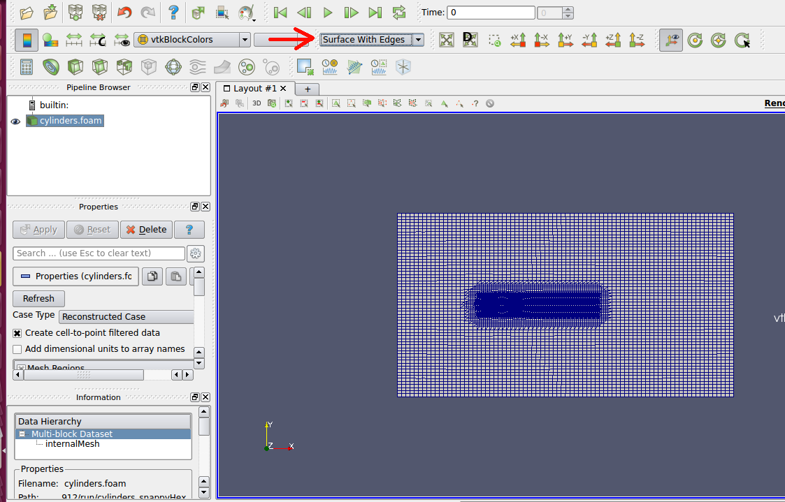
Let’s open Paraview to view the mesh. First it is necessary to create a .foam file. Type nano cylinders.foam into the terminal and press “enter”. Then press “ctrl + o”, “enter” and finally “ctrl + x”.

Now open Paraview by typing “paraview cylinders.foam”

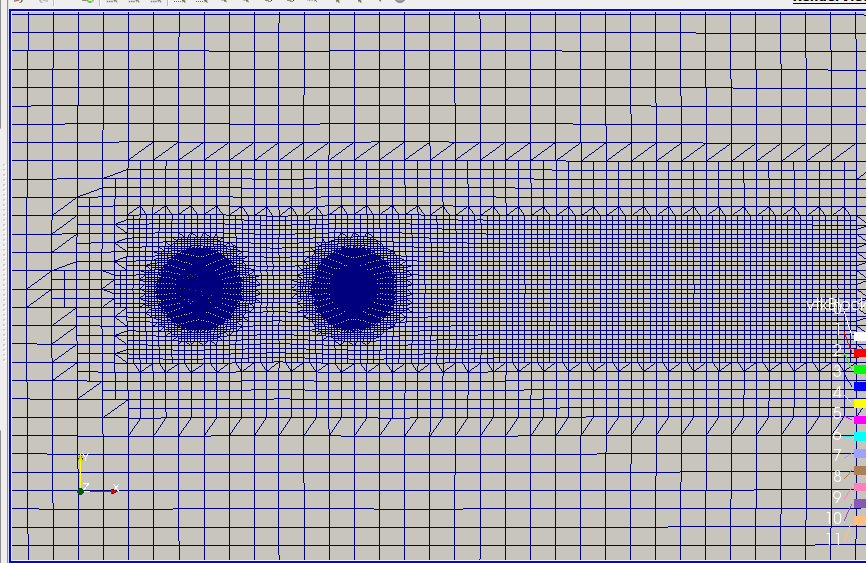
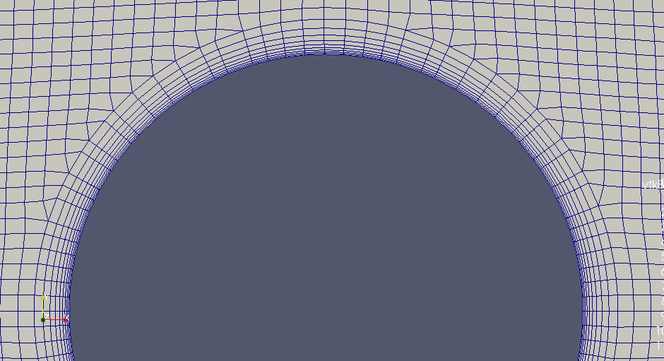
In Paraview, click “Apply” and then select “Surface With Edges” as shown below to preview the mesh. The resulting mesh with its different levels of refinement and its prisms layer on the walls can be seen in the images below.