

Meshing Tutorial for NACA0012 Profile – Two-dimensional


Meshing tutorial for NACA0012 profile – two-dimensional
Note:
- This tutorial has only didactic purpose, aiming to help beginners, and it does not guarantee quality of simulation results. Verification and validation of the results, and also the study of mesh refinement and other analyzes are left as responsibility of the user.
- This offering is not approved or endorsed by OpenCFD Limited, producer and distributor of the OpenFOAM software via www.openfoam.com, and owner of the OPENFOAM® and OpenCFD® trade marks.
- This tutorial was created within the context of an UFSC extension project and it is not approved by GMSH and OpenFOAM® developers.
- This tutorial was prepared by the undergraduate students Juliano Simon, Eduardo de Bittencourt Ribeiro and Widmark Kauê Silva Cardoso under the supervision of Filipe Dutra da Silva.
- Please quote this page if you use this material. Questions and suggestions can be sent to the contact addresses shown at the end of this page.
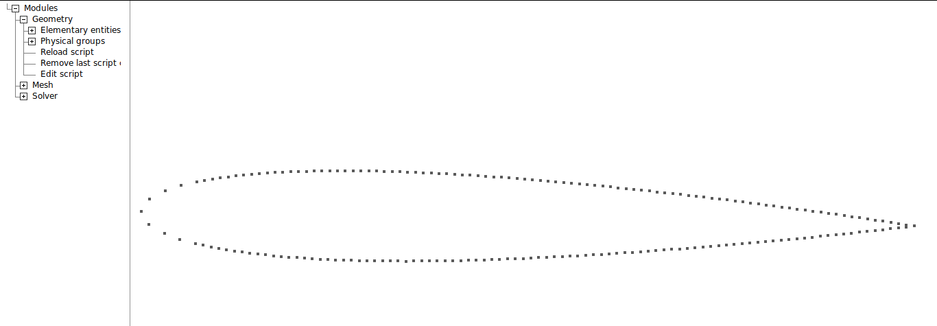
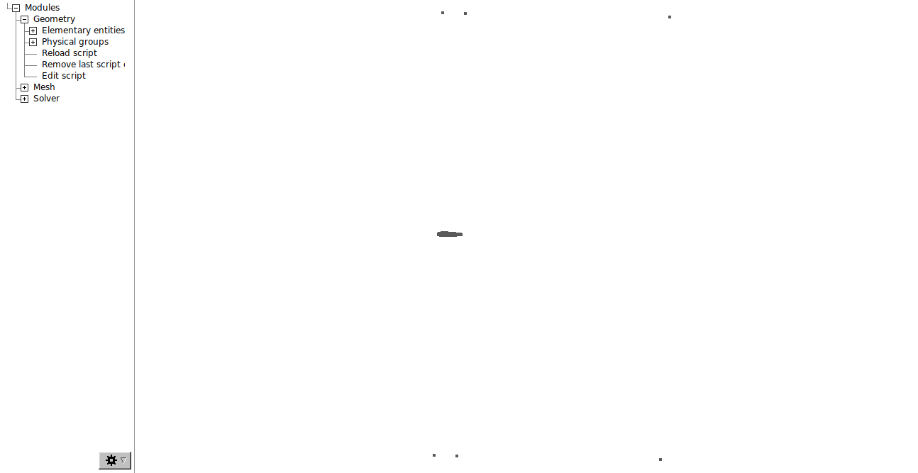
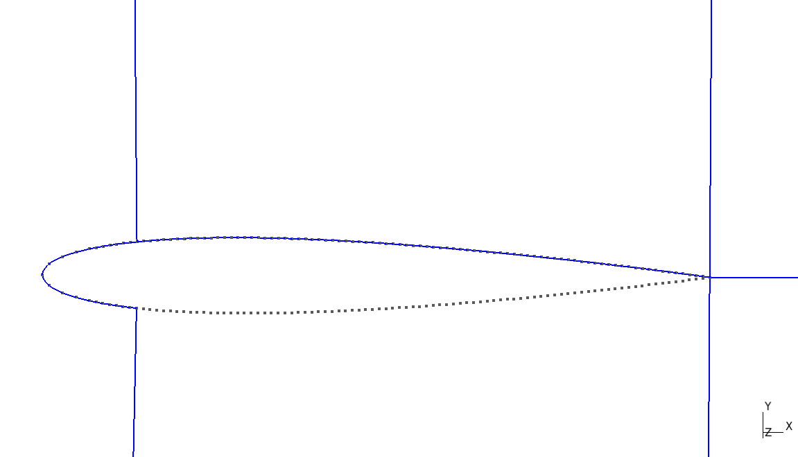
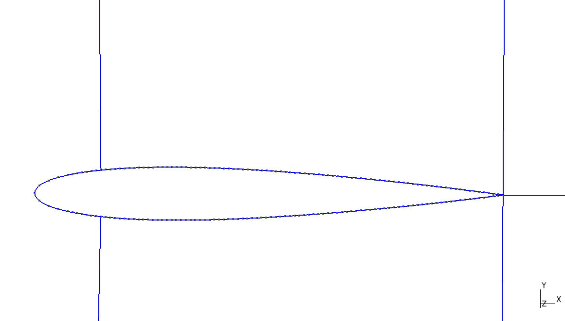
This tutorial will present the procedure to generate a 2D structured mesh (C-grid) for NACA 0012 airfoil, using the Gmsh code. There are two ways of using Gmsh: through the commands of the graphical interface of the software or editing the script with extension .geo, which is generated by the software. Both ways of using the software will be shown here. To open the script, go to Modules→Geometry and click Edit script.
First, it is necessary to load the points that are required to generate the profile lines. These points must be written in the .geo file as shown below:
Point(number) = {x, y, z, 1.0};
You can use an external code to write the coordinates in the required format, considering the large number of points. For this tutorial, the sequence of points can be found at the link naca.
The next step is to create the points located at the boundaries of the computational domain. The domain shape is shown at the beginning of this tutorial. To facilitate the possible need to change the size of this domain, several parameters will be defined using variables.
// MODELING VARIABLES

// domain
a = 10;
b = 10;
t = 1;

// number of elements
n1 = 0;
n2 = 0;
n3 = 0;
n4 = 0;

// increase rate
A = 0;
B = 0;
C = 0;
D = 0;
//====================================================
The number of elements and increase rate variables will be discussed futher down in this tutorial. Airfoil points can be added just below this first code.
Now it is possible to build the points that will form the computational domain, in the .geo file, write:
// DOMAIN

//Points
Point(199) = {a, -b, 0, t};
Point(201) = {a, b, 0, t};
Point(202) = {0, b, 0, t };
Point(204) = {0, -b, 0, t};
Point(205) = {1, -b, 0, t};
Point(206) = {1, b, 0, t};
Point(207) = {a, 0, 0, t};
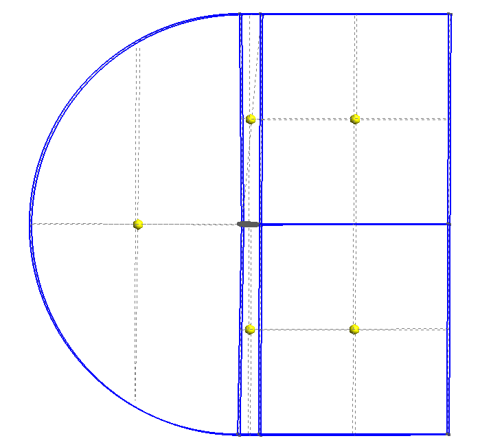
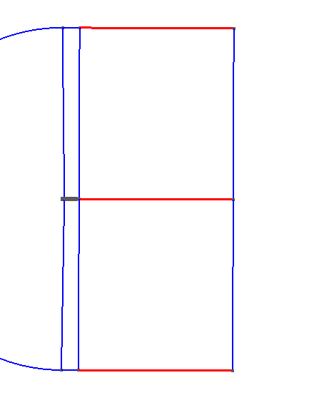
The next step is to connect the points that will define the mesh. Go to Modules→Geometry → Elementary entities → Add → Line and select the two points you want to connect. Connect the points as shown in the images.
The .geo code should be as shown below:
//Shape
Line(207) = {204,205};
Line(208) = {205,199};
Line(210) = {201,206};
Line(211) = {206,202};
Line(213) = {204, 185};
Line(214) = {15, 202};
Line(215) = {100, 206};
Line(216) = {205,100};
Line(220) = {199, 207};
Line(221) = {207, 201};
Line(222) = {207, 100};
To complete the front part of the mesh, a half-circle will be made. To do this, select Modules → Geometry → Elementary entities → Add → Circle arc and select the top point, center point and bottom point.
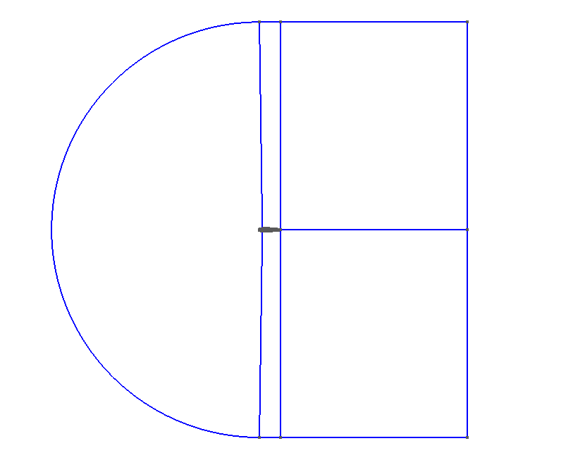
//+
Circle(223) = {204,1,202};
//===================================================
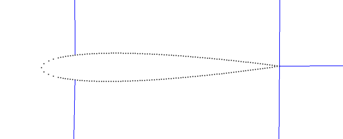
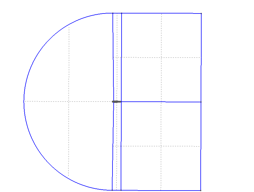
Then, we will create splines that define the airfoil shape. Go to Modules → Geometry → Elementay entities → Add → Spline and select the sets of points in the sequence shown in the figures below.
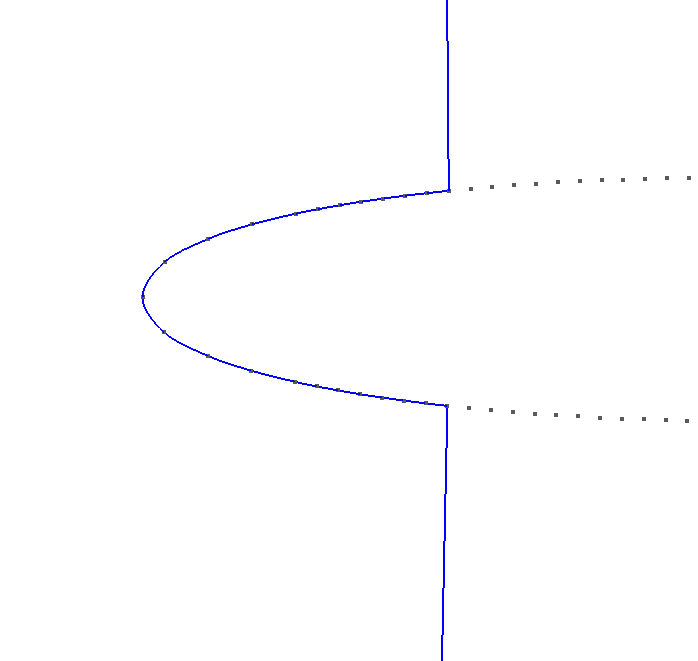
The .geo file should be as following:
// AIRFOIL SHAPE
Spline(217) = {185 , 186 , 187 , 188 , 189 , 190 , 191 , 192 , 194 , 196 , 198, 1 , 2 , 4 , 6 , 8 , 9 , 10 , 11 , 12 , 13 , 14 , 15}; //+
Spline(218) = {15 , 16 , 17 , 18 , 19 , 20 , 21 , 22 , 23 , 24 , 25 , 26 , 27 , 28 , 29, 30 , 31 , 32 , 33 , 34 , 35 , 36 , 37 , 38 , 39 , 40 , 41 , 42 , 43 , 44 , 45 , 46 , 47 , 48 , 49 , 50 , 51 , 52 , 53 , 54 , 55 , 56 , 57 , 58 , 59 , 60 , 61 , 62 , 63 , 64 , 65 , 66 , 67 , 68 , 69 , 70 , 71 , 72 , 73 , 74 , 75 , 76 , 77 , 78 , 79 , 80 , 81 , 82 , 83 , 84 , 85 , 86 , 87 , 88 , 89 , 90 , 91 , 92 , 93 , 94 , 95 , 96 , 97 , 98 , 99 , 100}; //+
Spline(219) = { 100 , 101 , 102 , 103 , 104 , 105 , 106 , 107 , 108 , 109 , 110 , 111 , 112 , 113 , 114 , 115 , 116 , 117 , 118 , 119 , 120 , 121 , 122 , 123 , 124 , 125 , 126 , 127 , 128 , 129 , 130 , 131 , 132 , 133 , 134 , 135 , 136 , 137 , 138 , 139 , 140 , 141 , 142 , 143 , 144 , 145 , 146 , 147 , 148 , 149 , 150 , 151 , 152 , 153 , 154 , 155 , 156 , 157 , 158 , 159 , 160 , 161 , 162 , 163 , 164 , 165 , 166 , 167 , 168 , 169 , 170, 171 , 172 , 173 , 174 , 175 , 176 , 177 , 178 , 179 , 180 , 181 , 182 , 183 , 184 , 185}; //+
//===================================================
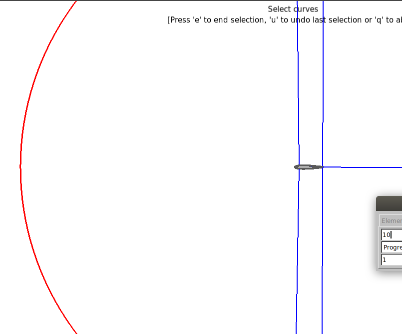
Now, the “Transfinite” function should be applied to the edges of the mesh. This will define the number of elements at each line of the block and the increase rate of the elements. Go to Modules → Mesh → Define → Transfinite → Curve and select the curves in that order:
- The front side curves of the airfoil and the front boundary of the mesh.
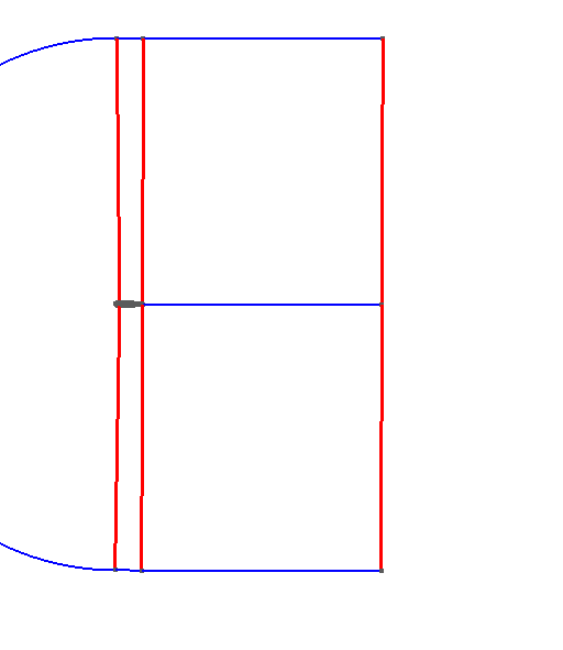
- The vertical lines.
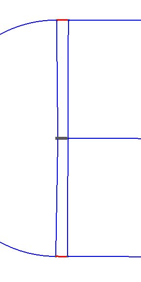
- The lateral lines of the airfoil and the boundaries of the mesh.
- The horizontal lines.
The .geo file should look like this:
// MESH
//Surfaces
Transfinite Curve {217, 223} = 10 Using Progression 1;
Transfinite Curve {220, 216, 213, 221, 215, 214} = 10 Using Progression 1;
Transfinite Curve {211, 218, 219, 207} = 10 Using Progression 1;
Transfinite Curve {210, 222, 208} = 10 Using Progression 1;
Next, you must adjust the number of volumes in each part of the mesh and the spacing of these volumes. To do so, use the variables created previously, apply these modifications to the .geo in the variables section:
// number of elements
n1 = 150;
n2 = 125;
n3 = 200;
n4 = 250;
// increase rate
A = 1;
B = 1.05;
C = 1;
D = 1.015;
Change the Transfinites of the edges as follows:
// MALHA
//Superfícies
Transfinite Curve {217, 223} = n1 Using Progression A;
Transfinite Curve {220, 216, 213, 221, 215, 214} = n2 Using Progression B;
Transfinite Curve {211, 218, 219, 207} = n3 Using Progression C;
Transfinite Curve {210, 222, 208} = n4 Using Progression D;
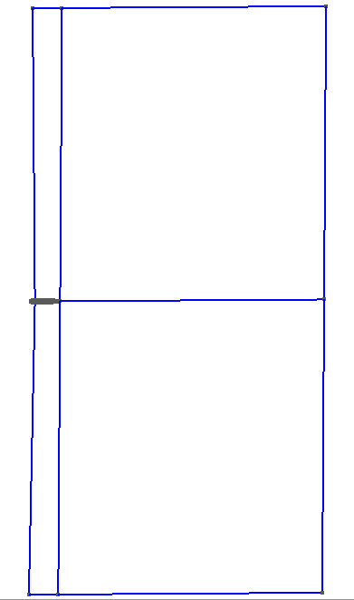
Now it is necessary to define the plans. Go to Modules → Geometry → Elementary entities → Add → Plane surface and select the curves that define each plane and press “e” to confirm. Example:
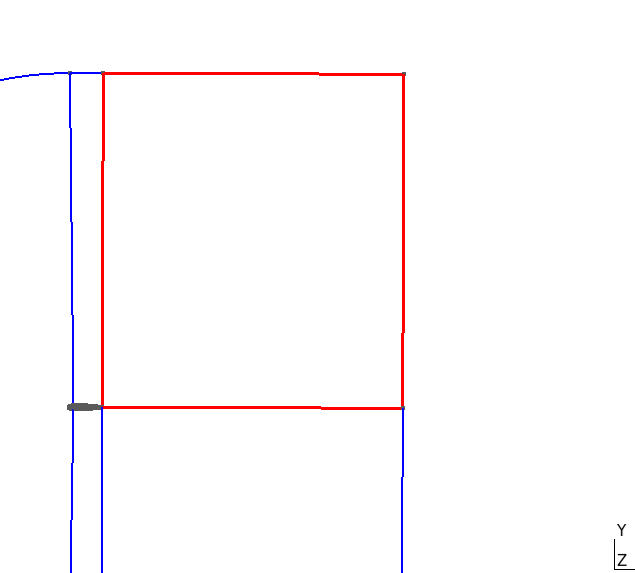
Doing this for each plane, the final result should be as shown below:
The .geo file should look like this:
//+
Curve Loop(1) = {210, -215, -222, 221};
Curve Loop(2) = {222, -216, 208, 220};
Curve Loop(3) = {207, 216, 219, -213};
Curve Loop(4) = {218, 215, 211, -214};
Curve Loop(5) = {223, 213, 217, 214};
//+
Plane Surface(2) = {2};
Plane Surface(3) = {3};
Plane Surface(4) = {4};
Plane Surface(5) = {5};
Now we will use the “Transfinite” function applied to the mesh faces. Go to Modules → Mesh → Define → Transfinite → Surface and select the faces pressing “e” to confirm. In the .geo file:
//+
Transfinite Surface {1};
Transfinite Surface {2};
Transfinite Surface {3};
Transfinite Surface {4};
Transfinite Surface {5};
Then go to Modules → Mesh → Define → Recombine and select all faces and press “e” to confirm. In .geo file:
//+
Recombine Surface {1, 2, 3, 4, 5};
//===================================================
Now the mesh will be extruded. Go to Modules → Geometry → Elementary entities → Extrude → Translate, select all faces and press “e” to confirm. The result should be like this:
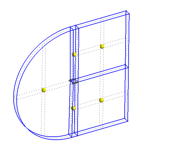
In .geo file, change the settings as shown below:
//EXTRUDE AND BOUNDARY NAMES
Extrude {0, 0, 1} {
Surface{5}; Surface{3}; Surface{2}; Surface{1}; Surface{4};
Layers{1};
Recombine;
}
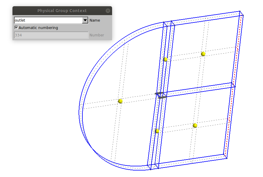
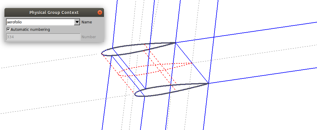
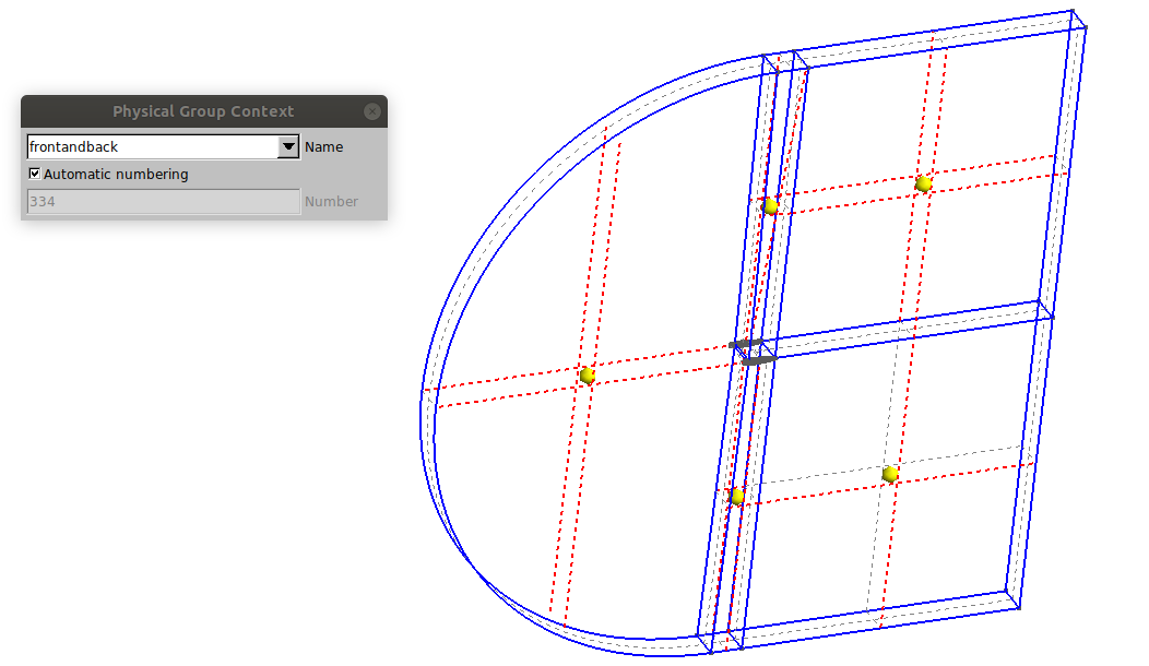
Finally, we must name each surface of the mesh that will be responsible for the boundary conditions. Go to Modules → Geometry → Physical Groups → Add → Surface. Select and name the surfaces in this order:
- inlet

- outlet
- airfoil
- front and back
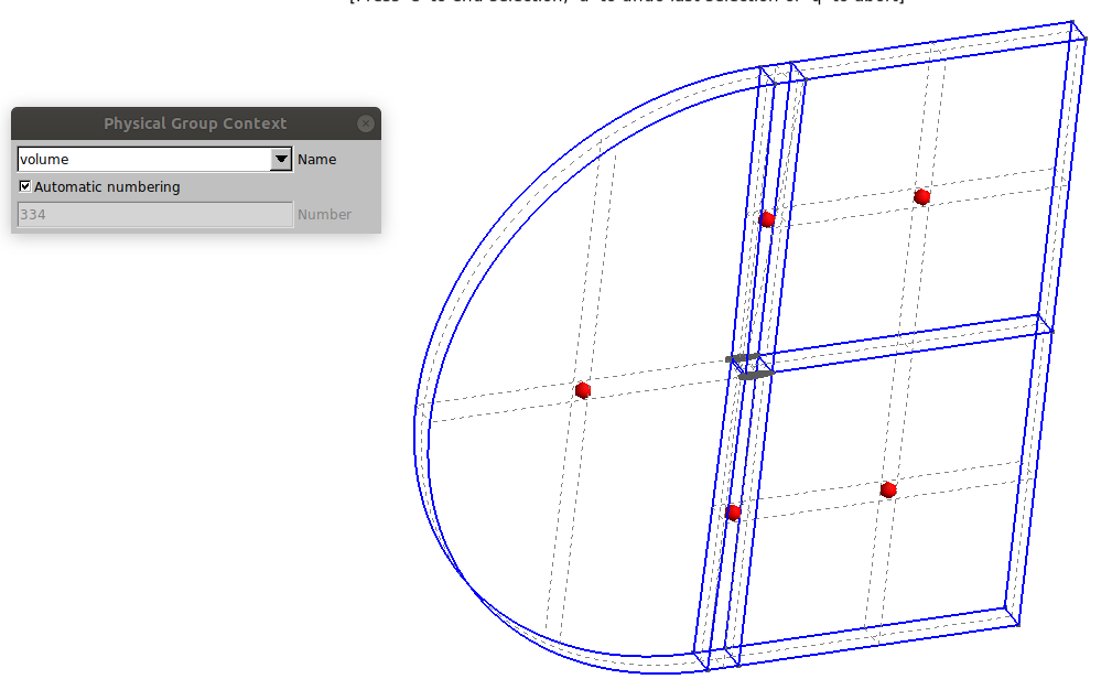
Now, go to Modules → Geometry → Physical Groups → Add → Volume and select all the volumes:
The result in .geo file should be as follows:
//+
Physical Surface("inlet") = {232, 328, 298, 284, 254};
Physical Surface("oulet") = {310, 288};
Physical Surface("airfoil") = {240, 320, 262};
Physical Surface("frontandback") = {245, 289, 267, 311, 333, 4, 1, 5, 3};
Physical Volume("volume") = {1, 2, 3, 4, 5};
At the end, add the command “Mesh 3;” in the .geo file and then the mesh creation is complete. To create the file that will be used in OpenFOAM, click on File → Export, choose the directory where you want to save, and save it with .msh extension. Then an “MSH Options” window will appear, select the “Version 2 ASCII” format and click on save.


